ProMini LoRaWAN Node
| ProMini LoRaWAN Node Release status: stable |
|
|---|---|
|
|
| Description | A LoRaWAN node based on the Arduino ProMini and the RFM95 LoRa module. |
| Last Version | 0.2 (2019-10-22) |
| Platform | Arduino ProMini |
| License | CC BY-SA 4.0 |
| Download | GitHub |
| Shop | Tindie |
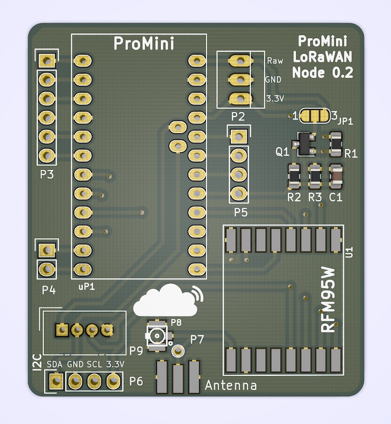
A LoRaWAN node based on the Arduino ProMini and the RFM95 LoRa module. Based on the original design by Doug Larue, but with some additional options:
- u.FL antenna connector
- Grove connector for I2C (can also be used for analog or digital signals)
- Circuitry to measure input voltage

Parts
Note: Antenna and LoRaWAN module are dependent on the local frequency band used for LoRaWAN. The selected items are meant for 868Mhz, which is the frequency band for Europe
Part |
Partnumber |
Source |
Notes |
|---|---|---|---|
PCB |
ProMini LoRaWAN Node PCB v0.2 |
||
Arduino |
Pro Mini, 3.3V, 8Mhz |
||
Antenna |
868Mhz SMA |
||
Antenna Connector |
SMA Edge mount |
||
u.FL surface mount |
To connect an SMA antenna, you will need a matching pigtail |
||
LoRa Module |
RFM95 868Mhz |
||
Battery Holder |
2x AA |
AliExpress |
|
Case |
Abzweigdose 75x75 |
Hardware store 1, [https://www.hornbach.de/shop/Spelsberg-Abzweigkasten-SD7-75x75-mm-33290701/6060827/artikel.html?] |
|
Input voltage measurement |
|||
MOSFET |
Q1: BSS 84 |
||
Resistors |
R1: 100k 0805 |
||
R2: 150k 0805 |
max input voltage for this R2/R3 combination: 16V |
||
R3: 10k 0805 |
|||
Capacitor |
C1: 100nF |
Attention - Common mistakes
We’ve made our fair share of mistakes already, so you don’t have to. Keep the following things in mind:
- If you want to use the I2C connector, make sure to solder pins A4 and A5 on the Arduino to the PCB. They are located a bit inside the module, not on the outside, and most Arduinos don’t ship with the necessary pin headers for these two pins, so they are easy to miss.
- Put your FTDI programmer into 3.3V mode before programming your node.
- Make sure you have an antenna connected to the board before powering it up. Otherwise your radio module might be damaged
Software
LMiC
To use the LMIC library with this PCB, use the following pin settings:
const lmic_pinmap lmic_pins = {
  .nss = 10,
  .rxtx = LMIC_UNUSED_PIN,
  .rst = LMIC_UNUSED_PIN,
  .dio = {4, 5, LMIC_UNUSED_PIN}
};
Also, some cheap Arduino ProMini boards have somewhat inaccurate timing,
so it’s recommended to tell the library to compensate for that by adding
the following line in your setup() routine:
LMIC_setClockError(MAX_CLOCK_ERROR * 1 / 100);
Project Ideas
Weather Station
Add a temperature and humidity sensor and watch the weather anywhere you like.
Example with a BME280 sensor (connected via I2C) to measure temperatue, humidity and atmospheric pressure: Source Code
Field Test Node
Add a display (I2C) and a few buttons to create a field test node similar to the Adeunis Field Test Device
Camper Van Monitor
Node with GPS, temperature and PIR sensor to “watch” your campervan while you’re away. Powered from your start or solar battery, which you can also monitor while you’re at it
Other examples
- TijnOnlijn has created a few examples with different sensors and put the code up on GitHub
- The folks at TTN Den Bosch created a sketch generator for ProMini-RFM95 LoRaWAN nodes. Make sure to choose the “RFM95 LMIC pins (10, 0, 4, 5, 7)” option for the radio: Code Generator, TTN Forums thread
Additional information
- Board can be powered directly from 2 AA batteries to the 3.3V input
- Full tutorial using this board by Frank Beks
Roadmap
- Replace the Arduino with a stock ATmega328
- Remove the 3.3V voltage measurement section as it can also be done internally on the ATmega (see 2)
- Add strain-relief holes for the power connection
- Add mounting holes
- Support a secure element, like the ATECC608
License
- Licensed under Creative Commons Attribution-ShareAlike 4.0 Unported License (CC BY-SA 4.0)
- Original work by Doug Larue