Powerhub XT60
| PowerHub XT60 Release status: beta |
|
|---|---|
|
|
| Description | DC distribution board using XT60 connectors |
| Last Version | 0.1 (2021-02-23) |
| License | CC BY-SA 4.0 |
| Download | GitHub Repo |
| Shop | Tindie |
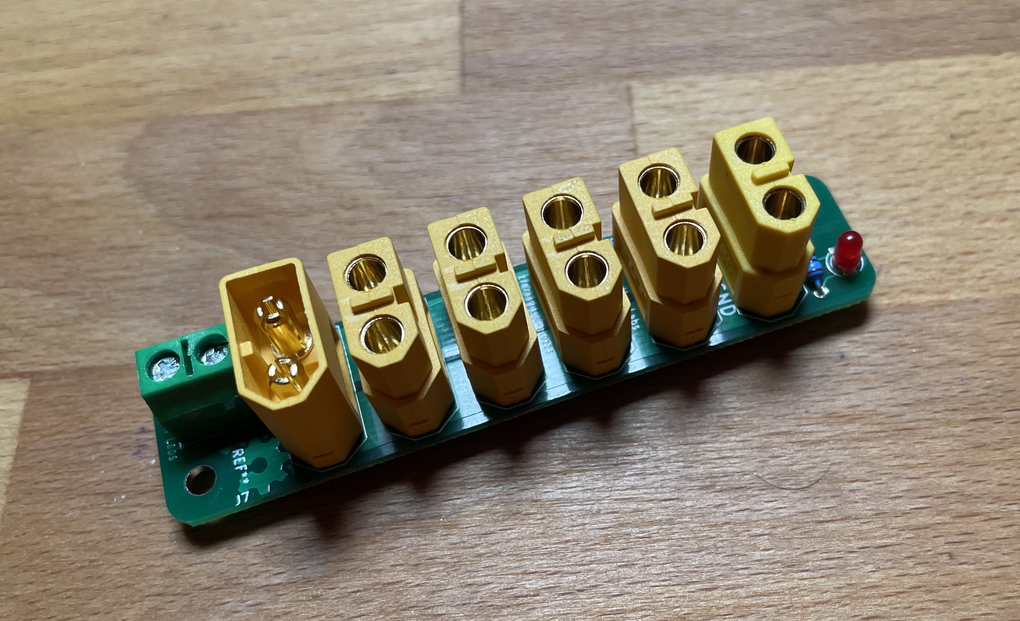
The PowerHub XT60 is a distribution board for up to 6 XT60 connectors (male or female), with optional power LED as well as screw terminals. It’s loosely based on the XT60 board by jesseaster, has only a single row of 6 XT60 connectors, a screw terminal, an optional status LED, and 2 M3 mounting holes.
XT60 connectors are really practical low-voltage DC power connectors. They are sturdy, have a really good friction fit and don’t cost a fortune. They are quite common in the RC world, but I have started using them in many other places, e.g. as a replacement for round DC jacks or car cigarette lighter plugs. They are also frequently used in the DIY powerwall community.
I have a number of devices that have an XT60 plug now, but not as many batteries. So I needed a power strip or some other kind of distribution. Looking around online, most of the stuff seemed rather sketchy, so I designed my own.
The PowerHub XT60 board can take up to 6 XT60 connectors, and you can freely mix and match male & female connectors. So you can do a “traditional” power strip with a single male power input, and up to 5 female power out sockets, or the other way around, e.g. to join multiple DIY powerbanks in parallel, with up to 5 male plugs and a single female plug.


Parts
Part |
Partnumber |
Amount |
Source |
Notes |
|---|---|---|---|---|
PCB |
powerhub XT60 PCB |
1 |
||
XT60 connector |
XT60 male or female |
6 |
Male and female connectors can be mixed as necessary |
|
Screw terminal |
2 pole, 5.08mm |
6 |
||
Indicator LED (optional) |
||||
LED |
LED 3mm |
1 |
||
Resistor |
R1: 1k |
1 |
Current Rating
XT60 connectors are supposed to be able to handle 60A. Not sure if that’s really the case, but it would be interesting to see how much current the PowerHub can handle.
In the sections between the XT60 connectors, the PCB traces are roughly 5.6mm wide. The PCBs on tindie have been made with 1oz of copper, and we have traces on both sides of the PCB.
According to this table by MCLPCB, and tolerating a 10° temperature increase, the plain PCB would be able to handle 8A per side, 16A in total. This is under the assumption that the PCB is fully populated with XT60 connectors, otherwise the holes will lead to a decrease in current capacity.
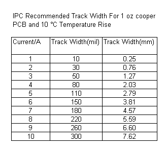
It’s recommended though to “enforce” the traces with solder all along the way, which would increase the current capacity of the PowerHub. How big the increase will be depends on the type and amount of solder used.
License
- Licensed under Creative Commons Attribution-ShareAlike 4.0 Unported License (CC BY-SA 4.0)