MatrixMix
| MatrixMix 4x4 Release status: stable |
|
|---|---|
|
|
| Description | A simple yet extendable matrix mixer |
| Last Version | 0.3 (2022-02-22) |
| License | CC BY-SA 4.0 (hw & docs) |
| Download | GitHub Repo |
| Shop | Lectronz, tindie |
A simple passive 4x4 matrix mixer. Extendable, and with sync passthrough.
Features
- 4 Inputs
- 4 Outputs
- Extension ports so extend the mixer to many more inputs, or add buffers/amplifiers to the outputs
- Sync passthrough, to support sync signals on the audio jack, like in Teenage Engineering Pocket Operator synths. Selectable on each input/output
Note: This is a passive mixer. So when you change one knob, there might be changes of loudness for the other channels as well. There’s no buffering between the channels, so it’s completely normal like that.
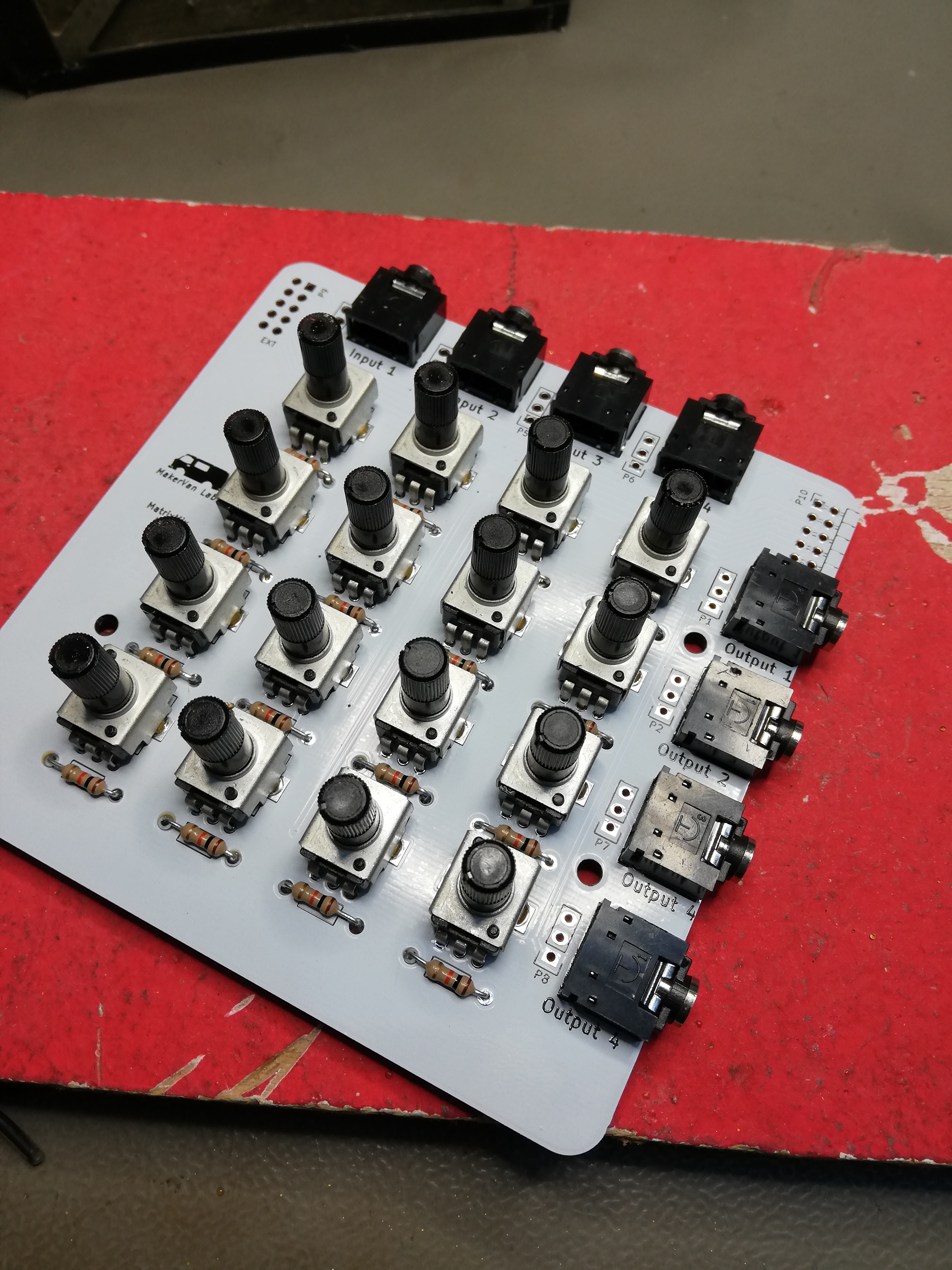
Pictures


Parts
Part of Circuit |
Part Number |
Distributor |
Amount |
Notes |
|---|---|---|---|---|
Potentiometer (50kΩ lin) |
Bourns PTV09A-4020S-B503 |
16 |
Suggested for v0.1 |
|
Potentiometer (50kΩ log) |
Bourns PTV09A-4020S-A503 |
16 |
Suggested for v0.2 |
|
3.5mm jacks |
EBSF 35 |
8 |
||
Resistors |
10kΩ |
16 |
You can populate P1-P8 with 3/4-pin 2.54mm headers, and mix the two channels of a stereo plug together, or pipe the second channel through to other devices, in a mode compatible with the Pocket Operator synths or similar modules. Here’s the different modes explained:
- No jumper means the second channel on the input jack is simply ignored.
- In the bottom position, the second channel on the input and output jacks is connected to a shared bus, which allows you to use the “sync” functionality between different devices that support it, like the Pocket Operators
- The the middle position on the four pin headers / top position on the three pin headers, both channels on the jack are connected together into the mixer channel. So for Inputs, L+R are combined into one Mono Channel. For the output, the same signal is sent to L+R.
- On the four pin headers, the top position allows you to work with a true stereo signal. If you place the jumper in the top position on channel 1, and no jumper on channel two, you can put a true stereo signal into Input Jack 2, and the two signals will be routed to mixer channel 1 and 2 separate from each other. Same logic for channel 3+4, and the outputs as well.
Connectors P9 and P10 can be used to connect multiple MatrixMix 4x4 boards together to create a matrix mixer with 8, 12 or even more inputs.
Versions
v0.1
This is an early prototype version of the MatrixMix 4x4 PCB. As such, it has one fun error in it: All potentiometers are backwards. So you have to turn each knob counterclockwise to make things louder. It’s a little unusual, but also kind of fun. Note though, that normally you would use logarithmic pots for audio signal. When soldering the PCB as is, this does not make much sense. So use linear pots instead (There are reverse logarithmic pots, but they are hard to come by).
One alternative is to flip the board upside down and solder the pots from the back side. That works quite well, just your inputs are now on the bottom (or your outputs on the left, depending on your flip). Make sure to solder the 3.5mm jacks in as originally intended, otherwise the sync-passthrough does not work anymore.
- Potentiometers are wired the wrong way, they all turn the wrong way
- 10k Pots and 10k mixing resistors don’t turn things all the way down
v0.2
Potentiometer orientation is fixed, and with proper values (50kΩ pots + 10kΩ mixing resistors) this thing is lots of fun.
v0.3
Fixed sync pinout, and add an option to use half the input / output jacks as true stereo inputs/outputs.
v0.4 (in planning)
- Add option to use 6.35mm jacks (1/4”)