LoRaWAN Battery Monitor
| LoRaWAN Battery Monitor Release status: experimental |
|
|---|---|
|
|
| Description | LiPo battery monitor to regularly check cell voltages |
| Last Version | 0.1 (2021-01-03) |
| Platform | ATMega328 |
| License | CC BY-SA 4.0 |


|
|
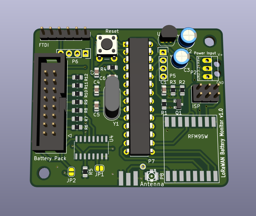
The LoRaWAN Battery Monitor is a LoRaWAN connected device based on the ATMega328 LoRaWAN Node to automatically measure the individual cell voltages of a Lithium Ion battery pack (up to 7S)
- lorawan_battery_monitor_01
 lorawan_battery_monitor_02
 lorawan_battery_monitor_03
 lorawan_battery_monitor_04
 lorawan_battery_monitor_05
Parts
Note: Antenna and LoRaWAN module are dependent on the local frequency band used for LoRaWAN. The selected items are meant for 868Mhz, which is the frequency band for Europe
Part |
Partnumber |
Amount |
Source |
Notes |
|---|---|---|---|---|
PCB |
LoRaWAN Battery Monitor PCB v0.1 |
1 |
- |
|
Microcontroller |
ATMega 328P-PU |
1 |
||
IC socket |
28pin |
1 |
||
Quartz |
8Mhz, HC49U-S |
1 |
||
Resistor |
R4: 10k 0805 |
1 |
||
Capacitors |
C4, C5: 22pF |
2 |
||
C6, C7: 100nF |
2 |
|||
Reset button |
SW1 |
1 |
||
Measurement |
||||
Resistor |
R5: 10k 0805 |
1 |
||
R6: 33k 0805 |
1 |
|||
R7: 75k 0805 |
1 |
|||
R8: 110k 0805 |
1 |
|||
R9: 160k 0805 |
1 |
|||
R10: 200k 0805 |
1 |
|||
R11: 240k 0805 |
1 |
|||
R12: 270k 0805 |
1 |
|||
Multiplexer |
U4: 74HC 4051 (SO-16) |
1 |
||
Voltage regulator for >3.3V input |
||||
Voltage Regulator |
U3: 3.3V, LDO, TO-92 -> LP2950-3.3 |
1 |
||
Capacitor |
C2, C3: 4,7µF Elko, >16V |
2 |
||
LoRa Modem section |
||||
Antenna |
868Mhz SMA |
1 |
||
Antenna Connector |
SMA Edge mount |
1 |
||
u.FL surface mount |
1 |
To connect an SMA antenna, you will need a matching pigtail |
||
LoRa Module |
RFM95 868Mhz |
1 |
||
Input voltage measurement |
||||
MOSFET |
Q1: BSS 84 |
1 |
||
Resistors |
R1: 100k 0805 |
1 |
||
R2: 150k 0805 |
1 |
max input voltage for this R2/R3 combination: 16V |
||
R3: 10k 0805 |
1 |
|||
Capacitor |
C1: 100nF |
1 |
||
Connectors |
||||
ISP |
J1: 2x3, 2.54mm |
1 |
2x4 connector is much cheaper than 2x3, but you can simply cut off one section |
|
Pin headers |
P3, P5, P6, P9, P10 |
(many pins) |
Just get one long row, and cut off those you need |
|
Screw terminals (Power In) |
P2 (outer pins): 2 pole, 5.08mm |
1 |
only if using voltage regulator |
|
Battery connector |
J2: 14pin |
1 |
Notes
- Splitting the voltage divider as I did didn’t work out, due to the
protection diodes and other circuitry within the 4051. There have to
be full voltage dividers “in front” of the multiplexer, basically
adding a 10kΩ resistor to ground on R6-R12. This leads to continuous
power consumption. Scaling up the resistors should help though.
- Recommendation on twitter was to use the BQ76930 chip by TI as an alternative. Looks very interesting, but I think I’ll go with the voltage dividers for now. Power consumption shouldn’t be that big of a deal in this case.
Links
- HackADay.io project
- Building the Prototype Twitter Thread (archive, original was here but now defunct)
- Fixing things Twitter thread (archive, original was here but now defunct)
License
- Licensed under Creative Commons Attribution-ShareAlike 4.0 Unported License (CC BY-SA 4.0)